High-Speed Pneumatic Actuator Testing Protocol
Systematic measurement of dynamic performance under acceleration limits
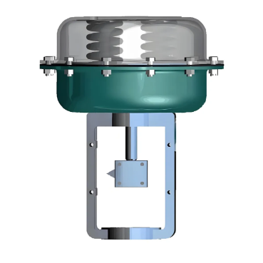
1. Setup & Instrumentation
Sensors: Install high-frequency accelerometers (1000+ Hz) on actuator shaft to capture angular acceleration (α). Encoders (1000+ PPR) track rotational position.
Data Acquisition: Use DAQ systems (16-bit resolution) to record pressure, flow, and motion signals.
2. Standard Test Procedures
Step Input Test: Apply sudden pressure ramps (0→6 bar in <50ms). For 100mm stroke, expect 5000–8000 rad/s² peak α.
Ramp Input Test: Vary pressure linearly (0–6 bar over 100ms). Deviations >10% indicate airflow limits.
Load Sweep: Test with 0–100% rated torque. Acceleration drop should be <20% at full load.
3. Critical Metrics
Time to Peak Acceleration: Measure duration to reach 90% of peak α (target <10ms).
Thermal Runaway: Monitor housing temperature during 100 cycles/min.
Temperatures >60°C indicate excessive friction.
Airflow Correlation: 10% airflow increase should yield ~7% higher acceleration (laminar flow).
4. Failure Mode Testing
Overpressure Tests: Gradually increase to 150% rated pressure (e.g., 6→10 bar).
Resonance Detection: Sweep 50–200 Hz frequencies.
Avoid operation where efficiency drops >30%.
5. Analysis & Optimization
Plot α-t curves to identify friction peaks (>20% steady-state α spikes).
Use CFD simulations to optimize port sizes if acceleration plateaus.
Benchmark against ISO 15552 standards.
If you want to learn more about low-priced products, please visit the following website: www.xm-valveactuator.com