Introduction
Pneumatic actuators are essential components in modern automation and industrial systems, converting compressed air energy into mechanical motion. Renowned for their reliability, simplicity, and cost-effectiveness, they play a pivotal role in industries ranging from manufacturing and robotics to oil and gas. This article provides a comprehensive exploration of pneumatic actuators, addressing their design, operational principles, types, applications, and future trends.

1. Definition and Overview
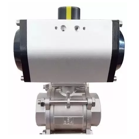
A pneumatic actuator is a mechanical device that uses compressed air to generate linear or rotary motion. It serves as an "energy converter," transforming the potential energy stored in pressurized gas into kinetic energy to perform tasks such as opening/closing valves, moving robotic arms, or clamping objects.
1.1 Key Characteristics
- Power Source: Compressed air (typically 40–120 psi or 3–8 bar).
- Motion Types: Linear (push/pull) or rotary (angular displacement).
- Operational Speed: Rapid response times (milliseconds to seconds).
- Force Output: Ranges from a few Newtons to over 100 kN, depending on design.
1.2 Historical Context
Pneumatic systems date back to the first industrial revolution, where they powered machinery in factories. Modern actuators evolved in the mid-20th century with advancements in materials, sealing technologies, and automation controls.

2. Core Components of a Pneumatic Actuator
Understanding the internal structure is critical to grasping how pneumatic actuators function. Key components include:
2.1 Cylinder
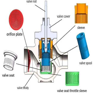
The cylinder is a sealed chamber where compressed air acts on a piston or diaphragm. It is typically made of lightweight aluminum, stainless steel, or engineered plastics for corrosion resistance.
2.2 Piston or Diaphragm
- Piston: A sliding component that moves linearly within the cylinder. Sealed with O-rings or lip seals to prevent air leakage.
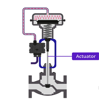
- Diaphragm: A flexible membrane (e.g., rubber or PTFE) that deforms under pressure, often used in low-force applications like control valves.
2.3 Actuator Shaft (Stem)
The shaft transfers motion from the piston/diaphragm to the external load. In linear actuators, it extends or retracts; in rotary actuators, it rotates.
2.4 Seals and Bearings
- Seals: Prevent air leakage and contamination. Common materials include nitrile rubber (NBR) and fluorocarbon (FKM).
- Bearings: Reduce friction in rotary actuators, enhancing efficiency and lifespan.
2.5 Control Valves
Directional control valves (e.g., solenoid valves) regulate airflow into and out of the actuator. They determine the direction, speed, and force of motion.
2.6 Accessories
- Position Sensors: Provide feedback for closed-loop control.
- Cushioning Devices: Absorb impact at the end of strokes to reduce wear.
- Air Preparation Units: Filters, regulators, and lubricators (FRL) ensure clean, dry air supply.
3. Working Principle of Pneumatic Actuators
The operation of pneumatic actuators hinges on the principles of fluid dynamics and force generation via pressurized gas.
3.1 Basic Physics
- Force Generation: Force is calculated as , where is air pressure and is the piston/diaphragm area.
- Boyle’s Law: At constant temperature, pressure and volume are inversely related ().
3.2 Step-by-Step Operation
- Air Supply: Compressed air enters the actuator via a control valve.
- Pressure Application: Air pushes against the piston or diaphragm, creating motion.
- Motion Transfer: The actuator shaft moves linearly or rotates, driving the load.
- Exhaust Phase: Spent air is released through exhaust ports, resetting the actuator.
3.3 Single-Acting vs. Double-Acting Actuators
- Single-Acting: Air pressure moves the piston in one direction; a spring returns it. Ideal for fail-safe operations.
- Double-Acting: Air alternates between two chambers for bidirectional motion. Offers higher force and precision.
4. Types of Pneumatic Actuators
Pneumatic actuators are categorized by motion type, design, and application.
4.1 Linear Actuators
-
Rod-Type Actuators: Feature an extendable rod for pushing/pulling loads.
- Telescopic Actuators: Multi-stage rods for long strokes.
- Diaphragm Actuators: Use a flexible diaphragm for low-force, precise control (e.g., regulating valves).
4.2 Rotary Actuators
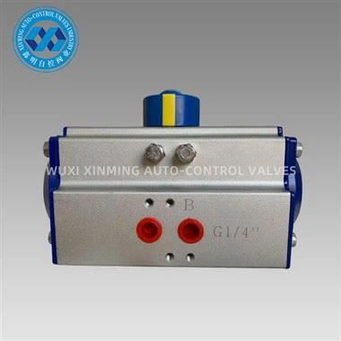
- Rack-and-Pinion: A linear piston drives a pinion gear to produce rotary motion (e.g., 90° valve rotation).
- Vane Actuators: A rotating vane inside a chamber generates torque (compact, low torque).
- Scotch-Yoke: Converts linear motion to rotary via a sliding yoke mechanism (high torque for large valves).
4.3 Specialty Actuators
- Grippers: Jaw-like actuators for grasping objects in robotics.
- Rodless Actuators: Use magnetic or band mechanisms for compact linear motion.
5. Advantages of Pneumatic Actuators
- High Speed: Rapid actuation suits high-cycle applications.
- Durability: Minimal wear due to non-contact operation (air cushions components).
- Safety: No fire risk, ideal for explosive environments (ATEX certified).
- Cost-Effective: Lower initial and maintenance costs compared to hydraulic/electric systems.
- Clean Operation: No risk of fluid leaks, making them suitable for food/pharmaceutical industries.
6. Limitations and Challenges
- Limited Precision: Air compressibility causes "springiness," requiring feedback for precise positioning.
- Energy Inefficiency: Compressors consume significant energy; leaks exacerbate waste.
- Noise Pollution: Exhaust air generates noise (often mitigated with silencers).
- Environmental Impact: Compressors contribute to carbon emissions unless powered renewably.
7. Industrial Applications
Pneumatic actuators are ubiquitous across industries due to their versatility:
7.1 Manufacturing and Automation
- Assembly Lines: Actuating presses, clamps, and conveyor systems.
- Packaging: Sealing, labeling, and filling machines.
7.2 Process Control
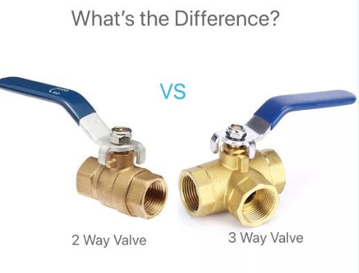
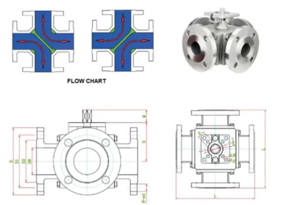
- Valve Automation: Controlling ball, butterfly, and gate valves in chemical plants and water treatment.
- Pressure Regulation: Adjusting airflow in HVAC systems.
7.3 Robotics
- Pick-and-Place Robots: Grippers and arms for handling components.
- Collaborative Robots (Cobots): Lightweight actuators for safe human interaction.
7.4 Transportation
- Aerospace: Landing gear, cargo doors, and brake systems.
- Railways: Door controls and braking mechanisms.
7.5 Healthcare
- Medical Devices: Pneumatic prosthetics and ventilator systems.
8. Selecting the Right Pneumatic Actuator
Key factors to consider:
- Force/Torque Requirements: Calculate based on load and safety factors.
- Stroke Length/Rotation Angle: Match to the application’s motion range.
- Operating Environment: Temperature, humidity, and hazardous area certifications.
- Control Needs: Open-loop vs. closed-loop (feedback-dependent) systems.
9. Innovations and Future Trends
- Smart Pneumatics: IoT-enabled actuators with predictive maintenance and energy monitoring.
- Energy-Efficient Designs: Reduced air consumption via improved sealing and valve tech.
- Hybrid Systems: Combining pneumatic speed with electric precision (e.g., servo-pneumatic actuators).
- Eco-Friendly Materials: Biodegradable seals and recyclable components.
10. Case Study: Pneumatic Actuators in Oil and Gas
10.1 Application: Subsea Valve Control
- Challenge: Operating valves at extreme depths (high pressure, corrosive environment).
- Solution: Double-acting, corrosion-resistant actuators with titanium components.
- Outcome: Reliable valve operation with minimal maintenance over 10+ years.
11. Conclusion
Pneumatic actuators remain a cornerstone of industrial automation, offering unmatched speed, simplicity, and adaptability. While challenges like energy efficiency persist, advancements in smart technology and material science promise to enhance their role in sustainable, Industry 4.0-driven systems. Engineers must balance performance requirements, environmental impact, and lifecycle costs when integrating these devices into modern workflows.
If you want to learn more about low-priced products, please visit the following website: www.xm-valveactuator.com