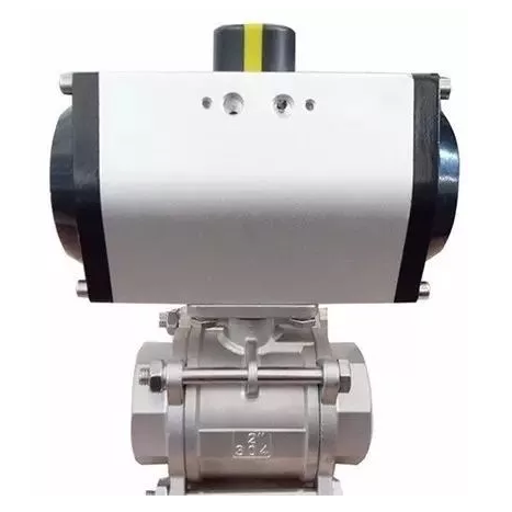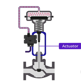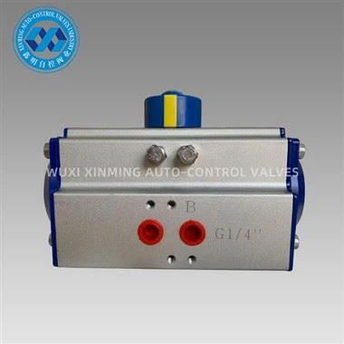
Pneumatic actuators are fundamental components in industrial automation, converting compressed air energy into mechanical motion. Whether used in valve control, robotics, or material handling, understanding the pneumatic actuator diagram is essential for engineers, technicians, and maintenance personnel. This article offers an in-depth look at interpreting pneumatic actuator diagrams and understanding their key components.

1. What Is a Pneumatic Actuator Diagram?
A pneumatic actuator diagram is a schematic representation that illustrates how compressed air flows through the actuator system to produce linear or rotary motion. It provides insight into air supply connections, internal chambers, seals, springs, and control ports, often using standardized pneumatic symbols according to ISO 1219 or DIN 24300.
These diagrams are essential for:
-
System design
-
Troubleshooting
-
Installation and maintenance
-
Safety analysis
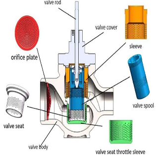
2. Core Components Illustrated in the Diagram
Here are the key components typically shown in a pneumatic actuator diagram:
a. Air Supply Port (A/B or 1/2)
-
These are the entry and exit points for compressed air.
-
In double-acting actuators, both ports are active and control motion in two directions.
-
In spring-return actuators, one port controls the motion while the spring returns it.
b. Piston or Diaphragm
-
The internal element that moves due to air pressure.
-
Represented by a circular or rectangular shape inside a cylinder body.
c. Cylinder Housing
-
Encases the piston and defines the stroke.
-
Diagrams often show seals and cushioning zones.
d. Spring (if applicable)
-
Found in single-acting actuators.
-
Drawn as a coil or zigzag, indicating stored mechanical energy used to return the actuator.
e. Position Indicator or Feedback Linkage
-
Sometimes included in the diagram, especially for control valve applications.
-
Indicates the actuator’s position to a controller or feedback system.
f. Directional Control Valve
-
Shown as a separate block or part of the circuit.
-
Directs air to specific actuator chambers, enabling motion control.
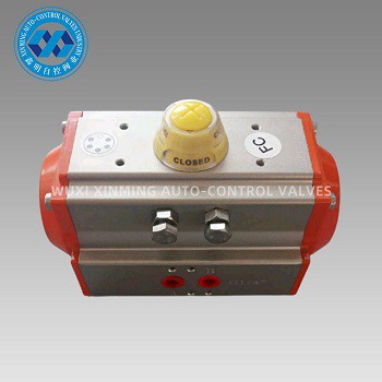
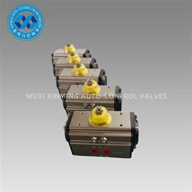
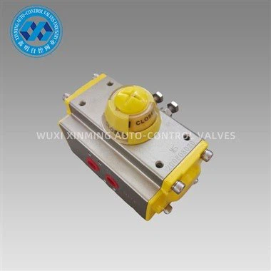
3. Types of Pneumatic Actuators in Diagrams
3.1 Linear Actuators
-
Motion is in a straight line.
-
Diagrams show a piston inside a cylinder, with ports at either end.
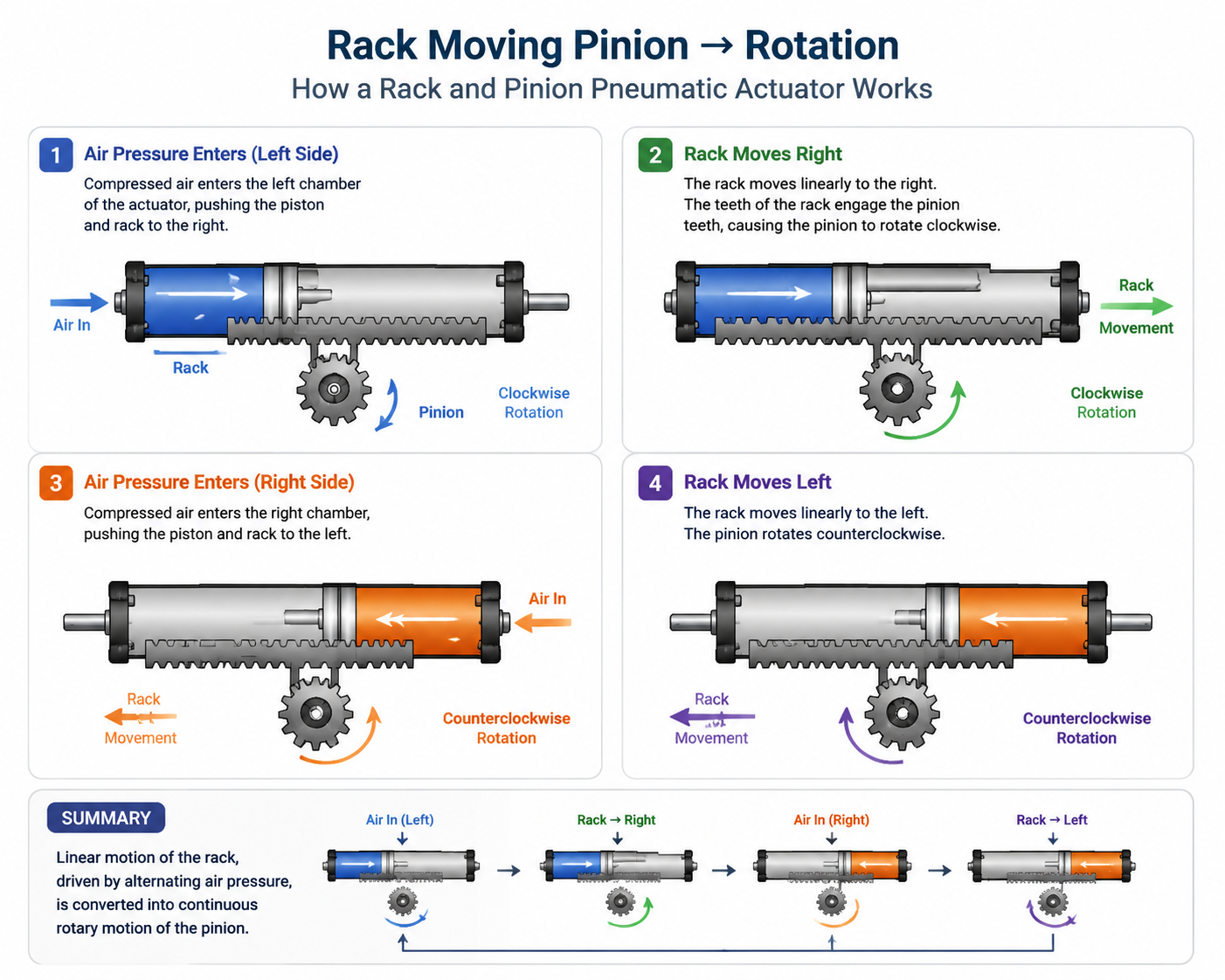
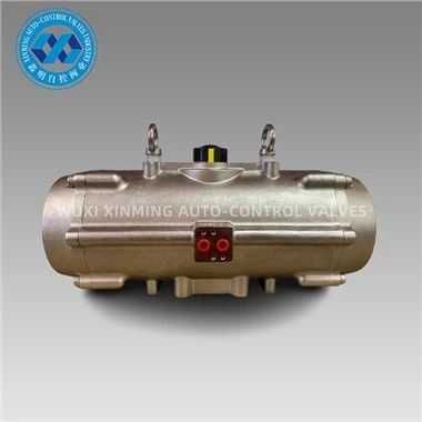
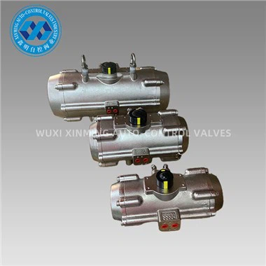
3.2 Rotary Actuators
-
Provide angular motion.
-
Rack and pinion or vane-type mechanisms are typically shown.
Note: A pneumatic rotary actuator diagram includes components like:
-
Rotary shaft
-
Air chambers on either side
-
Pinion gear and rack (if applicable)
4. Example: Interpreting a Double-Acting Pneumatic Actuator Diagram
A basic double-acting actuator diagram includes:
-
Two air ports (labeled A and B)
-
A piston in the center with rod ends extending outward
-
Seals around the piston and rod
-
Compressed air entering Port A causes the piston to move right
-
Compressed air entering Port B causes it to return left
The directional control valve upstream determines which port receives air.
5. Why These Diagrams Matter
Understanding pneumatic actuator diagrams enables:
-
Accurate installation and commissioning
-
Faster troubleshooting
-
Safer emergency maintenance
-
Better control system integration with PLCs or DCS
6. Conclusion
A pneumatic actuator diagram is more than just a technical drawing—it’s a blueprint for motion. Mastering how to read and interpret these diagrams is a crucial skill in process automation, manufacturing, and mechanical design. Whether working with linear or rotary actuators, familiarity with these schematics ensures precise control, enhanced reliability, and efficient operation.
If you want to learn more about low-priced products, please visit the following website: www.xm-valveactuator.com