Introduction
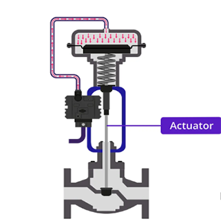
When selecting a pneumatic actuator for a valve or automation system, understanding its torque output is critical. A pneumatic actuator torque table is a reference chart provided by manufacturers that shows the actuator’s output torque under various supply pressures. This data ensures proper sizing, prevents underperformance, and improves system reliability.
In this article, we will explain:
-
What a pneumatic actuator torque table is
-
How torque is calculated
-
How to interpret torque tables
-
Key considerations when selecting an actuator
What is a Pneumatic Actuator Torque Table?
A pneumatic actuator torque table is a data chart that lists the output torque values of an actuator at different air supply pressures. It typically includes:
-
Model or series of the actuator
-
Operating pressure range (e.g., 2.5 bar to 8 bar)
-
Breakaway torque (torque required to start valve movement)
-
Running torque (torque required to keep valve moving)
-
End torque (torque at the end of stroke)
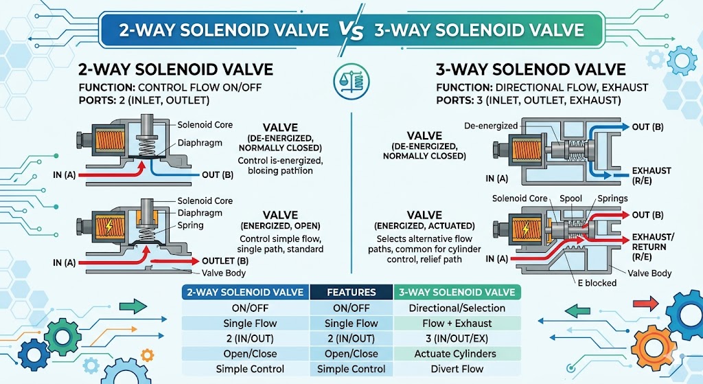
Manufacturers often provide separate tables for double-acting and spring-return pneumatic actuators because their torque outputs differ.
Why Torque Data Matters
Choosing the correct torque capacity is essential for:
-
Reliable Valve Operation – Ensuring the actuator can overcome valve friction and pressure.
-
Avoiding Oversizing – Preventing unnecessary costs and air consumption.
-
Extending Equipment Life – Reducing wear by matching torque to valve requirements.
-
Safety Compliance – Meeting industry safety standards for automated valve systems.
How to Read a Pneumatic Actuator Torque Table
Here’s a simplified example for a double-acting actuator:
| Supply Pressure (Bar) | Output Torque (Nm) |
|---|---|
| 2.5 | 80 |
| 3.5 | 112 |
| 5.5 | 176 |
| 7.0 | 224 |
Reading tips:
-
Find the required valve torque from valve specifications.
-
Add a safety factor (usually 20–30%).
-
Match the required torque to the table’s closest higher value.
For spring-return actuators, tables are more detailed because torque decreases during stroke as the spring expands.
Torque Calculation Formula
For double-acting pneumatic actuators:
For spring-return actuators, the calculation must also account for spring force at different positions.
Factors Affecting Torque Output
-
Air Supply Pressure – Lower pressure means lower torque.
-
Piston Diameter – Larger pistons produce higher torque.
-
Actuator Type – Rack-and-pinion vs. scotch-yoke mechanisms have different torque curves.
-
Temperature & Air Quality – Extreme temperatures or poor air quality can reduce efficiency.
-
Spring Tension – In spring-return actuators, stronger springs reduce torque output.
Pneumatic Actuator Torque Table Example
Below is a simplified spring-return example:
| Supply Pressure (Bar) | Start Torque (Nm) | End Torque (Nm) |
|---|---|---|
| 5.0 | 120 | 80 |
| 6.0 | 144 | 104 |
| 7.0 | 168 | 128 |
Note: The torque decreases because the spring’s resistance increases as it returns the actuator to its fail position.
Selection Tips
-
Check Valve Torque Requirements – Including breakaway and running torque.
-
Add a Safety Margin – Typically 25% above maximum required torque.
-
Consider Operating Conditions – Pressure fluctuations, temperature, and media.
-
Review Manufacturer’s Torque Table – Always use official data.
-
Account for Future Changes – If the system pressure might change, choose an actuator that can handle it.
Conclusion
A pneumatic actuator torque table is an essential reference tool for engineers, maintenance teams, and procurement specialists. By understanding how to read and apply torque table data, you can ensure accurate actuator sizing, reliable valve performance, and optimized system efficiency. Always combine torque table analysis with proper safety factors and real-world operating conditions for the best results.
If you want to learn more about low-priced products, please visit the following website: www.xm-valveactuator.com