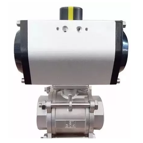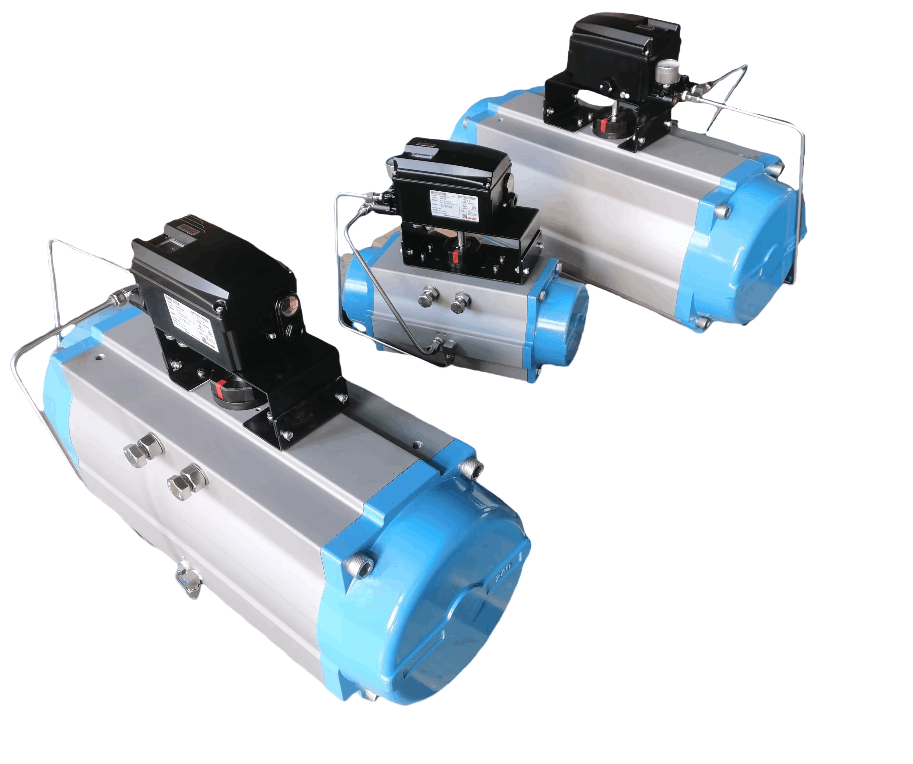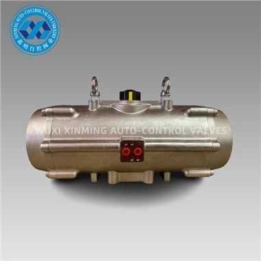
Double-Acting Pneumatic Actuator Connection
Standardized interface ensures secure mechanical coupling and efficient torque/force transmission between actuator and valve
1
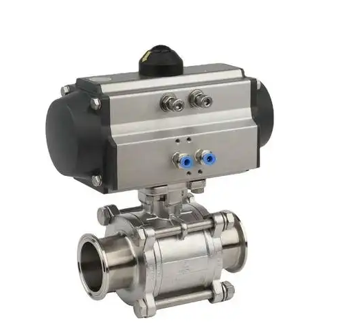
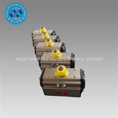
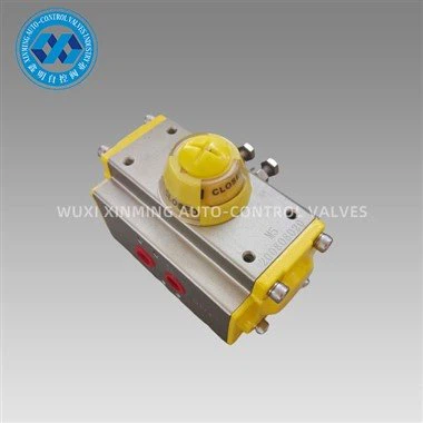
Mounting Interface
Most actuators and valves use ISO 5211 standards for mounting flanges, featuring bolt holes and a drive shaft alignment system.
Actuator's base flange bolts directly to the valve's top flange
Precise alignment ensured by a pilot to prevent misalignment
Standardized dimensions ensure cross-manufacturer compatibility
2
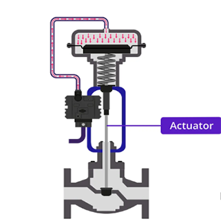
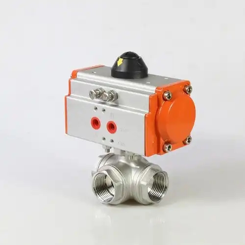
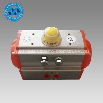
Shaft Connection
The actuator's output shaft connects to the valve's stem via a coupling, transferring torque for rotation or linear movement.
Common coupling types: clamp-style, split, or rigid
Accommodates minor alignment variations
Secures components while allowing torque transmission
3
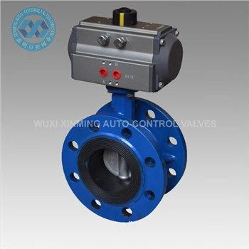
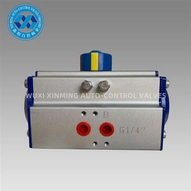
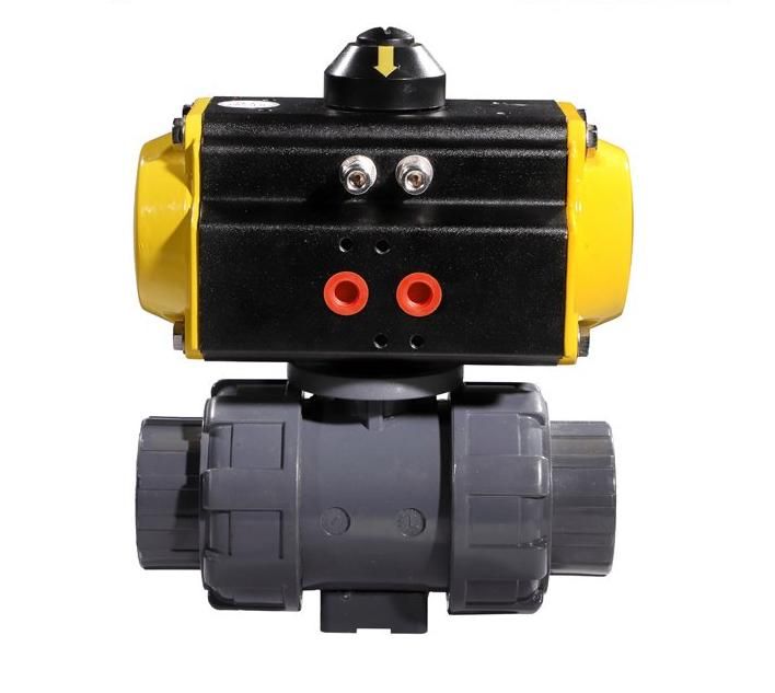
Air Supply Lines
Compressed air lines connect to the actuator's ports to control piston movement.
Lines connect via standard fittings to actuator ports
Linked to control valves regulating air flow
Air flow direction determines extension/retraction
4
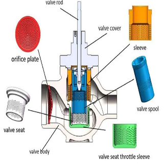
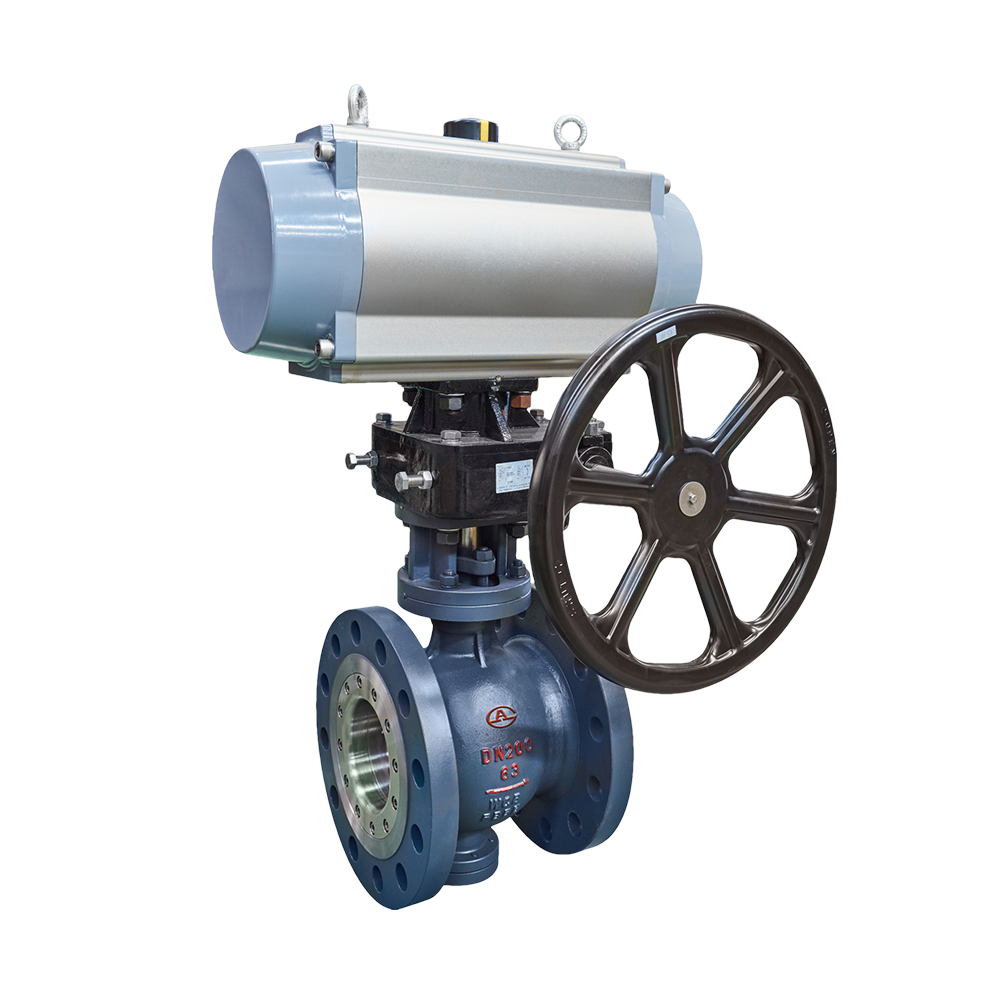
Accessories Integration
Additional components can be mounted to enhance functionality and monitoring.
Positioners or limit switches mount on actuator
Use same flange pattern for compatibility
Electrical connections to control system
Provides feedback on valve position
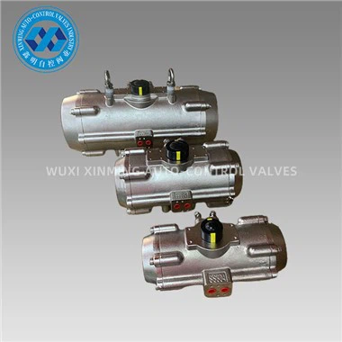
This standardized approach ensures compatibility across manufacturers, reliable operation, and ease of installation/maintenance.
If you want to learn more about low-priced products, please visit the following website: www.xm-valveactuator.com