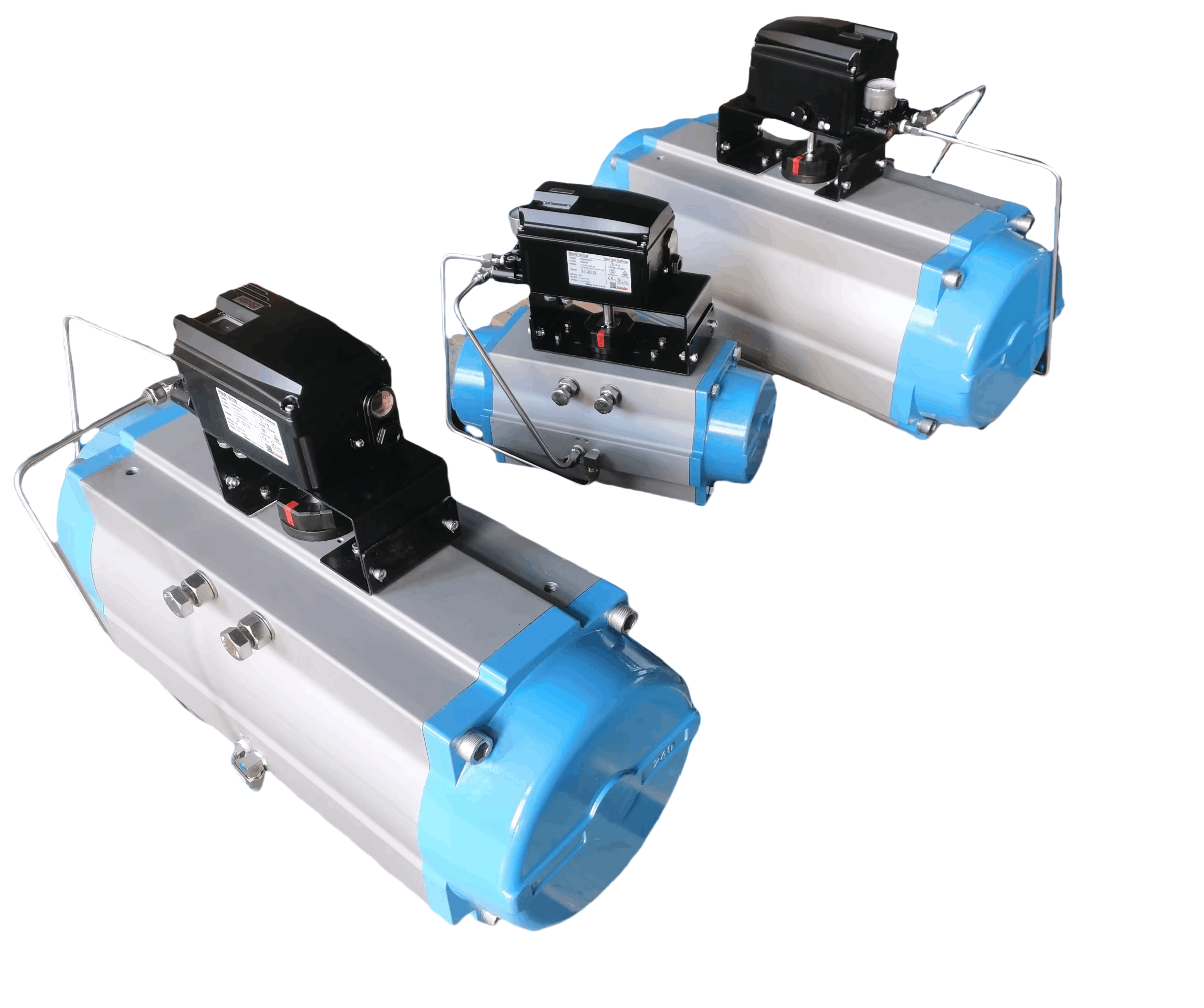
Pneumatic Actuator Adjustment Procedure
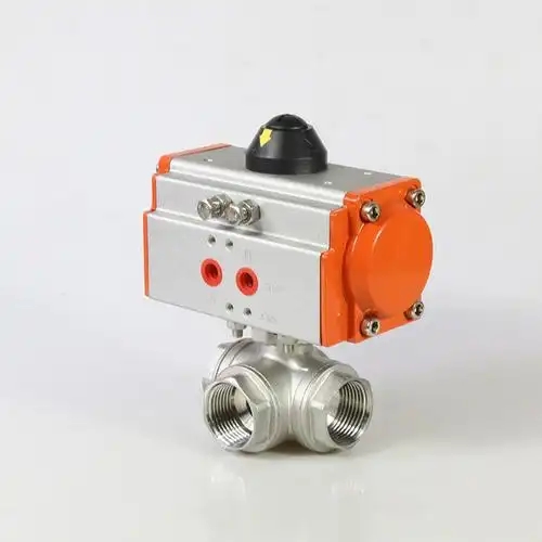
1 Preparation Before Adjustment
- Disconnect the actuator from the air supply and valve to prevent accidental movement
- Consult the manufacturer's manual to identify stroke adjustment components
- Locate adjustment points such as stop screws or limit switches
- Use appropriate tools to avoid damaging hardware
Always ensure the system is depressurized before beginning any adjustment procedure.
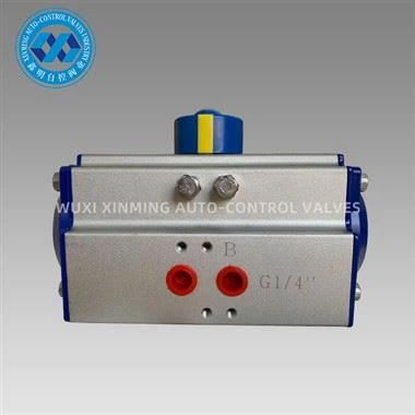
2 Mechanical Stop Adjustment
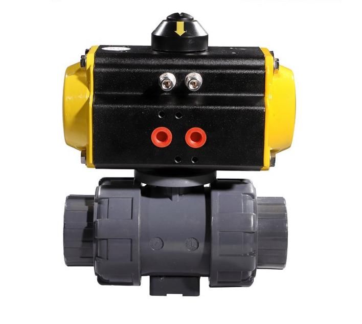
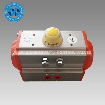
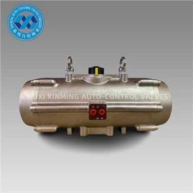
- Locate the open and closed position stop screws on the actuator housing
- For the closed position: manually rotate the valve to its fully closed state
- Tighten the closed stop screw until it contacts the actuator's lever arm
- Repeat for the open position, ensuring a precise 90-degree rotation between stops
Use a torque wrench when adjusting stop screws to prevent overtightening and thread damage.
3 Pneumatic Limit Setting
- For actuators with pneumatic limit valves, adjust pressure settings
- Set cutoff pressures to restrict airflow at full stroke
- Use a pressure gauge to set precise open/closed position pressures
- Ensure the actuator stops smoothly without overshooting
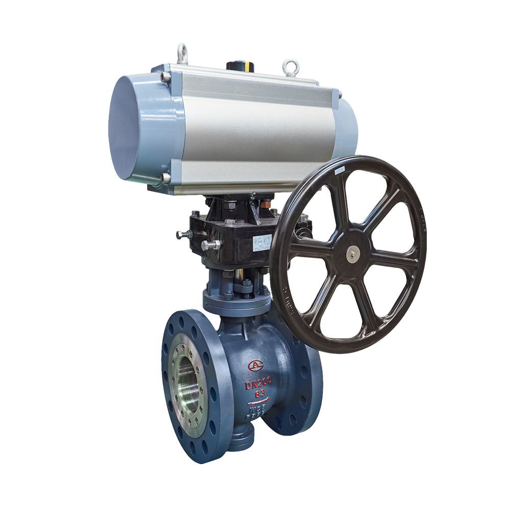
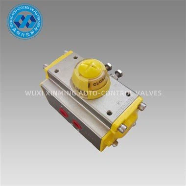
4 Calibration and Testing
- Reconnect the air supply and test full cycles
- Use a protractor to verify exact 90-degree stroke
- For misalignment: fine-tune stops incrementally
- Avoid over-tightening to prevent jamming
5 Final Checks
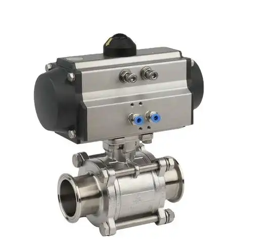
- Confirm actuator alignment with valve's open/closed positions
- Check for air leaks from adjusted components
- For automated systems: recalibrate positioners to sync with new stroke limits
- Ensure precise control throughout the operating range
Document all adjustments made for future reference and maintenance records.
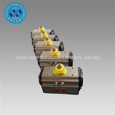
If you want to learn more about low-priced products, please visit the following website: www.xm-valveactuator.com