Introduction
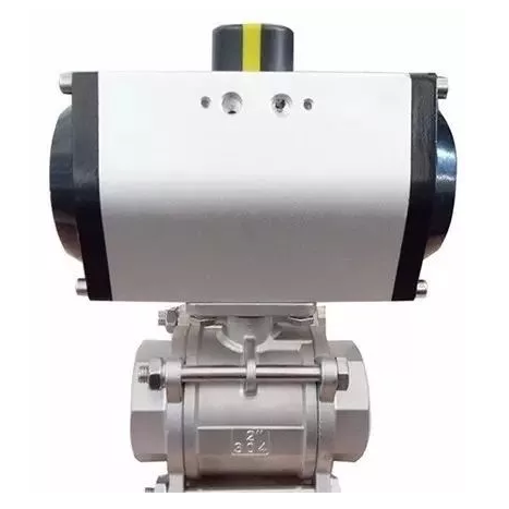
A rack and pinion pneumatic actuator is one of the most widely used rotary actuators in industrial automation. It converts compressed air energy into controlled rotary motion, typically used to operate quarter-turn valves such as ball valves, butterfly valves, and plug valves.

Due to its compact structure, high torque output, fast response time, and cost-effectiveness, the rack and pinion design has become a standard solution in industries including oil & gas, water treatment, chemical processing, power generation, and food manufacturing.
In this article, we will explain:
-
The basic working principle
-
Internal structure and components
-
Double-acting vs. spring-return operation
-
Torque generation mechanism
-
Advantages and limitations
-
Typical industrial applications
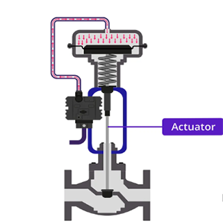
1. Basic Working Principle
At its core, a rack and pinion pneumatic actuator transforms linear motion into rotary motion.
When compressed air enters the actuator chamber:
-
Air pressure pushes one or two pistons linearly.
-
The pistons are connected to racks (linear gear teeth).
-
The racks engage with a central pinion gear.
-
Linear movement of the racks rotates the pinion.
-
The pinion turns the valve stem, opening or closing the valve.
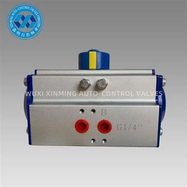
Simple Working Diagram (Top View)
When air enters Port A:
-
Pistons move inward
-
Racks rotate the pinion clockwise
When air enters Port B:
-
Pistons move outward
-
Pinion rotates counterclockwise
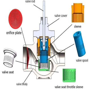
2. Internal Components Explained
A rack and pinion actuator consists of the following major components:
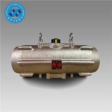
1. Actuator Body
-
Typically made from aluminum alloy or stainless steel
-
Houses internal moving parts
-
Often hard-anodized for corrosion resistance
2. Pistons
-
Two opposed pistons (in most designs)
-
Contain sealing rings (O-rings, wear bands)
-
Convert air pressure into linear force
3. Racks
-
Machined gear teeth integrated into piston backs
-
Engage directly with the pinion
4. Pinion Gear
-
Central rotating shaft
-
Transfers motion to valve stem
-
Supported by bearings or bushings
5. End Caps
-
Seal air chambers
-
Allow airflow direction control
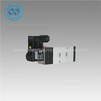
6. Air Ports
-
Typically NAMUR-standardized
-
Allow control via solenoid valves
3. Double-Acting Operation
A double-acting rack and pinion actuator uses compressed air for both opening and closing.
Operation Cycle:
Step 1: Opening
-
Air enters Port A
-
Pistons move inward
-
Pinion rotates (e.g., 90°)
Step 2: Closing
-
Air enters Port B
-
Pistons move outward
-
Pinion rotates back
Diagram – Double Acting
Key Features:
-
Higher torque output
-
Full control in both directions
-
Ideal for automated systems
-
Requires continuous air supply
4. Spring-Return (Single-Acting) Operation
A spring-return actuator uses compressed air in one direction and internal springs for return.
Structure Difference:
-
Springs installed on one or both piston sides
Operation:
Air Applied
-
Pistons compress springs
-
Pinion rotates (valve opens or closes)
Air Removed
-
Springs push pistons back
-
Valve returns to fail-safe position
Spring Return Diagram
Advantages:
-
Fail-safe functionality
-
Critical for safety systems
-
Ideal for emergency shutdown (ESD)
5. Torque Generation Mechanism
The torque output of a rack and pinion actuator depends on:
-
Air pressure (bar or psi)
-
Piston surface area
-
Rack-to-pinion gear ratio
-
Mechanical efficiency
Basic Force Formula:
Linear Force:
Where:
-
F = Force
-
P = Air pressure
-
A = Piston area
Torque Output:
Where:
-
r = Pinion radius
Important Note:
Unlike scotch yoke actuators, rack and pinion actuators typically provide relatively constant torque output throughout the stroke.
This makes them ideal for valves requiring stable torque across 0°–90° rotation.
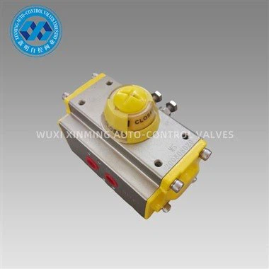
6. Stroke and Rotation Range
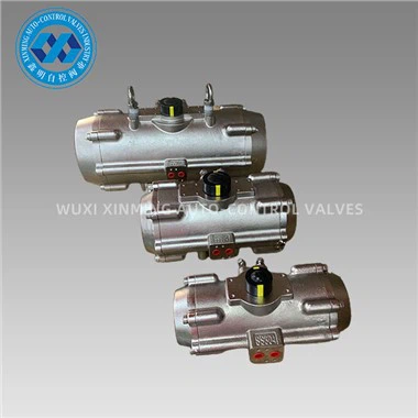
Most rack and pinion actuators are designed for:
-
90° rotation (standard quarter-turn valves)
-
Adjustable travel stops ±5°
-
Optional 120°, 135°, or 180° designs
Adjustable travel stops help:
-
Compensate for valve wear
-
Ensure precise shutoff
-
Prevent over-travel
7. Mounting and Standardization
Modern rack and pinion pneumatic actuators comply with international standards:
-
ISO 5211 – Valve mounting interface
-
NAMUR VDI/VDE 3845 – Solenoid mounting
-
NAMUR accessory interface – Limit switches & positioners
This standardization allows:
-
Easy installation
-
Interchangeability
-
Simplified maintenance
8. Advantages of Rack and Pinion Pneumatic Actuators
1. Compact Design
Small footprint compared to scotch yoke actuators.
2. Fast Response Time
Air-driven system allows rapid opening and closing.
3. High Reliability
Simple mechanical structure with few moving parts.
4. Cost-Effective
Lower manufacturing cost for small to medium torque ranges.
5. Balanced Load Distribution
Dual piston design improves torque symmetry.
9. Limitations
While highly versatile, rack and pinion actuators have some constraints:
-
Not ideal for extremely high torque (> large pipeline valves)
-
Torque curve is constant, not peak-at-start like scotch yoke
-
Requires clean, dry compressed air
-
Spring-return models have torque drop-off near end stroke
For very large valves (e.g., > DN600), scotch yoke actuators may be preferred.
10. Typical Industrial Applications
Rack and pinion pneumatic actuators are widely used in:
-
Oil & Gas pipelines
-
Water treatment plants
-
Chemical processing systems
-
Pharmaceutical production
-
Food & beverage facilities
-
HVAC automation
-
Marine systems
Common valve pairings:
-
Ball valves
-
Butterfly valves
-
Plug valves
-
Dampers
11. Maintenance and Service Life
To ensure long service life:
-
Use filtered, dry compressed air
-
Maintain correct lubrication
-
Inspect seals periodically
-
Check travel stop adjustment
-
Verify mounting alignment
High-quality actuators can achieve:
-
Over 1 million cycles (standard)
-
3–5 million cycles (premium models)
Conclusion
A rack and pinion pneumatic actuator is a robust, efficient, and widely adopted solution for quarter-turn valve automation. By converting linear piston movement into rotary output through a simple gear mechanism, it provides consistent torque, fast operation, and reliable performance.
Whether in double-acting or spring-return configuration, this actuator design offers flexibility for both general automation and safety-critical applications.
For most small to medium torque valve applications, rack and pinion pneumatic actuators remain the industry standard due to their balance of performance, cost-efficiency, and mechanical simplicity.
If you want to learn more about low-priced products, please visit the following website: www.xm-valveactuator.com