Achieving perfect synchronization between an actuator and a ball valve is critical for plant safety and operational efficiency. Improper mounting can lead to stem leakage, premature seal wear, or even catastrophic valve failure.
In this professional guide, we walk you through the essential steps to ensure your valve automation assembly is precise, secure, and ready for long-term service.
Phase 1: Pre-Installation Checklist
Before you begin, ensure that both the valve and the actuator are in the same orientation—usually the "Closed" position.
-
Verify the Mounting Pad: Most modern valves follow the ISO 5211 standard. Ensure the flange size (e.g., F05, F07, F10) on the actuator matches the valve's mounting pad.
-
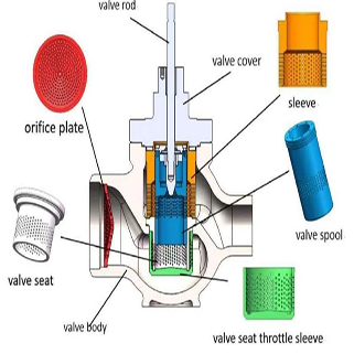
Inspect the Stem/Drive: Check if it is a "Double-D," "Square," or "Keyed" drive. If they don't match perfectly, you will need a customized drive adapter or bush.
-
Clean the Surfaces: Remove any debris, rust, or excess grease from the mounting interfaces.
Phase 2: The Mounting Process
Step 1: Install the Bracket and Coupler (If Required)
If the actuator is not directly mounted, you will need a mounting kit (bracket and coupler).
-
Secure the bracket to the valve body first.
-
Slide the coupler onto the valve stem. Ensure there is no "play" or looseness, as this causes hysteresis (lag) during operation.
Step 2: Align and Seat the Actuator

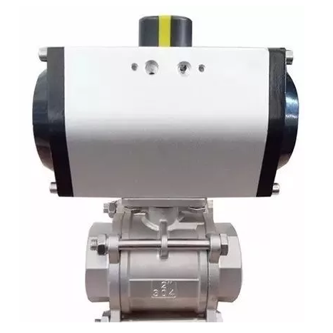
Lower the actuator (pneumatic or electric) onto the valve stem or coupler.
-
Pro Tip: If the bolt holes don't align perfectly, do not force them. Instead, slightly rotate the actuator to find the center. Forcing alignment can put side-load stress on the valve packing, leading to leaks.
Step 3: Secure the Fasteners
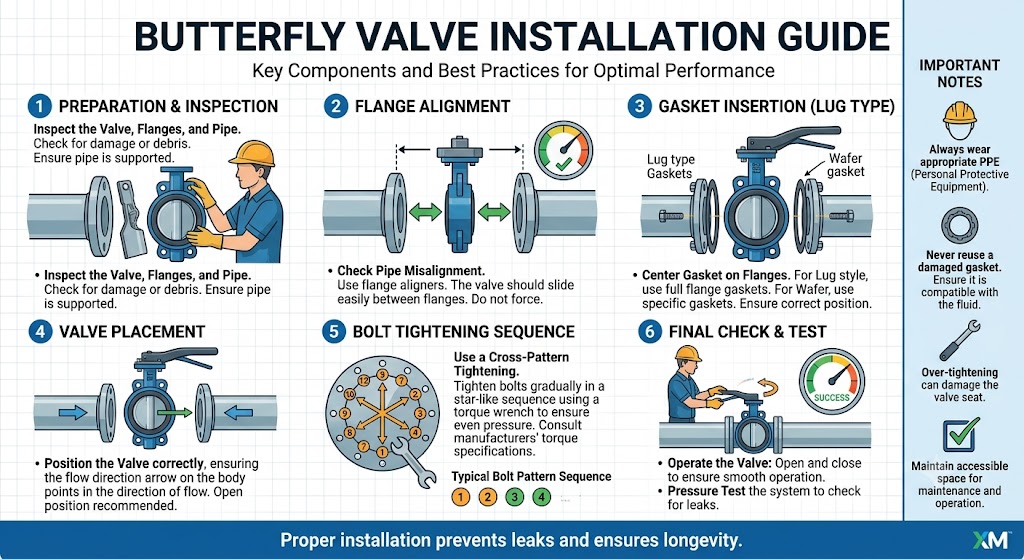
Insert the mounting bolts and tighten them in a star pattern (diagonal sequence). This ensures even pressure distribution across the mounting face. Use a torque wrench to meet the manufacturer's specified tightness.
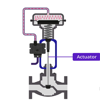
Phase 3: Calibration and Limit Adjustment
Mounting is only half the job. Calibration ensures the valve is 100% closed (preventing leaks) and 100% open (maximizing flow).

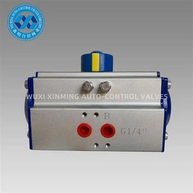
Step 4: Adjusting Travel Stops (For Pneumatic Actuators)
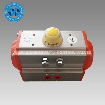
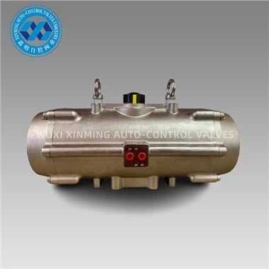
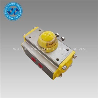
Most XM-Valve pneumatic actuators feature external travel stops.
-
Closing Adjustment: Turn the "Close" stop screw until the ball is perfectly perpendicular to the flow path.
-
Opening Adjustment: Turn the "Open" stop screw until the ball port is perfectly aligned with the valve body bore.
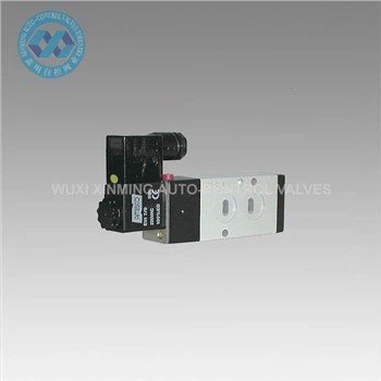
Step 5: Setting Limit Switches (For Electric Actuators)
If you are using an electric actuator, you must set the internal cam-operated limit switches.
-
Manually move the valve to the closed position.
-
Adjust the "Close" cam until it triggers the microswitch.
-
Repeat for the "Open" position. This prevents the motor from over-torquing and damaging the valve seats.
Phase 4: Final Testing and Verification
Before putting the assembly into the production line, perform a Dry Run:
-
Cycle the Valve: Operate the actuator 3–5 times. Observe for any jerky movements or unusual noises.
-
Check for Alignment: Ensure the stem remains centered throughout the 90-degree rotation.
-
Pressure Test: If possible, perform a seat leakage test to confirm the "Closed" position calibration is accurate.
Why Precision Mounting Matters
A poorly mounted actuator is the leading cause of valve packing failure. By following this professional calibration guide, you extend the lifespan of your hardware and reduce maintenance downtime.
Looking for Reliable Valve Automation Solutions?
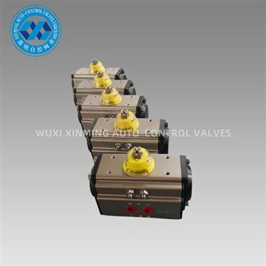
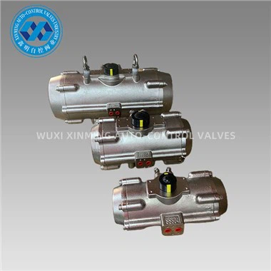
At XM-Valve, we provide high-quality Pneumatic Actuators, Electric Actuators, and ready-to-install Automated Ball Valve Packages. Our products are designed for easy mounting and precision control.
If you want to learn more about low-priced products, please visit the following website: www.xm-valveactuator.com