In industrial fluid systems, the Valve Flow Coefficient represents one of the most critical parameters for system design and optimization. Whether you are specifying control valves for a chemical plant, selecting ball valves for water distribution, or designing hydraulic systems, understanding Flow Factors is essential for achieving optimal performance and efficiency. This comprehensive guide explores everything engineers need to know about Cv and Kv values, from basic definitions to advanced sizing calculations.
The Flow Coefficient provides a standardized method for comparing valve capacity across different manufacturers and valve types. By mastering these concepts, engineers can prevent costly sizing errors, reduce energy consumption, and ensure reliable system operation across a wide range of applications including oil and gas, chemical processing, water treatment, and HVAC systems.

What is the Valve Flow Coefficient (Cv)?
The Valve Flow Coefficient (Cv) is an imperial measurement that quantifies the flow capacity of a valve under specific conditions. By definition, Cv represents the volume of water at 60°F (15.6°C) in US gallons that will flow through a fully open valve per minute with a pressure drop of 1 psi across the valve.
The mathematical relationship between flow rate and pressure drop allows engineers to predict system performance and select the appropriate valve size for their specific application requirements. Higher Cv values indicate greater flow capacity with minimal pressure loss, while lower values signify more restricted flow paths.
Understanding Cv Calculation Formula
For liquid service applications, the fundamental Cv calculation formula relates flow rate, specific gravity, and pressure drop. The basic equation enables precise valve sizing and performance prediction in industrial applications.
Where each parameter plays a specific role in determining valve performance:
- Cv: Flow Coefficient value representing valve capacity
- Q: Flow rate measured in US gallons per minute (GPM)
- SG: Specific Gravity of the fluid relative to water (water = 1)
- ΔP: Pressure drop across the valve measured in psi
Key Insight: When sizing control valves, always calculate the required Cv based on your maximum expected flow rate and acceptable pressure drop. Never select a valve based solely on pipe diameter, as this common mistake leads to inefficient system operation and increased operating costs.
What is the Flow Factor (Kv)?
The Flow Factor (Kv) serves as the metric equivalent to the imperial Cv system, providing a standardized method for valve sizing in regions using the International System of Units. The Kv value is defined as the flow rate of water in cubic meters per hour (m³/h) at temperatures between 5°C and 40°C, with a pressure drop of 1 bar across the valve.
Understanding the relationship between Cv and Kv is essential for engineers working on international projects or specifications that require conversion between measurement systems. Both parameters quantify the same physical property using different scales and reference conditions.
Cv to Kv Conversion Formula
The conversion between these two measurement systems follows well-established engineering relationships. These formulas enable accurate translation between imperial and metric specifications.
| Conversion Direction | Formula | Multiply By |
| Kv to Cv | Cv = 1.156 × Kv | 1.156 |
| Cv to Kv | Kv = 0.865 × Cv | 0.865 |
Why Valve Flow Coefficient Matters for System Design
Accurate valve flow coefficient calculations form the foundation of effective system design. Proper valve sizing based on Cv values prevents multiple operational problems that can compromise system performance and increase maintenance costs over the equipment lifecycle.
Consequences of Improper Valve Sizing
Selecting valves without proper flow coefficient analysis leads to significant operational issues:
- Oversized Valves: Valves with excessive Cv ratings relative to system requirements suffer from poor throttling characteristics, hunting behavior, and accelerated wear on actuators and valve seats due to excessive travel and control instability.
- Undersized Valves: Valves with insufficient flow capacity create severe pressure restrictions, forcing pumps to work beyond design specifications, reducing system efficiency, and potentially causing cavitation damage to internal components.
- Cavitation and Noise: High velocity flows through restricted valve openings generate cavitation, which erodes valve internals, creates disruptive noise, and significantly shortens equipment service life in industrial applications.
- Energy Inefficiency: Incorrectly sized valves increase pumping costs due to excessive pressure drops, resulting in higher operational expenses throughout the system lifetime.
Key Factors Influencing Flow Coefficient Values
Multiple design and operational factors affect the actual Cv rating of a valve in service. Understanding these influences enables more accurate sizing calculations and better system performance prediction.
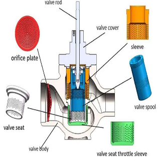
Valve Internal Geometry
Different valve designs offer distinctly different flow coefficients based on their internal flow paths:
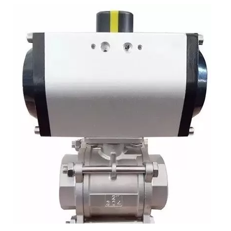
- Full-Port Ball Valves: Provide the highest Cv values with minimal flow restriction, making them ideal for applications requiring maximum flow capacity with minimal pressure loss.
- Butterfly Valves: Offer good flow coefficients in fully open position with compact design, suitable for large diameter applications in water distribution and HVAC systems.
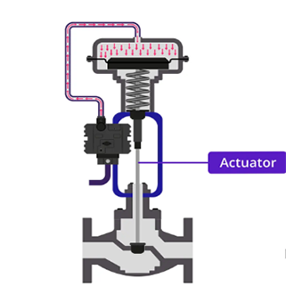
- Globe Valves: Feature lower Cv values due to S-shaped flow path that creates more pressure drop, but provide superior throttling performance for precise flow control applications.
- Gate Valves: Deliver high Cv values when fully open with minimal flow restriction, best suited for isolation rather than flow regulation duties.
Valve Opening Position and Flow Characteristics
Most manufacturer Cv specifications apply to the fully open position. As valves close, the effective flow coefficient changes according to the valve's inherent flow characteristic:
- Linear Characteristic: Flow coefficient changes proportionally with valve opening, providing consistent control sensitivity across the travel range.
- Equal Percentage: Each increment of valve opening produces an equal percentage change in Cv, offering finer control at low flow rates and stable control throughout the range.
- Quick Opening: Maximum flow is achieved with minimal stem travel, providing high Cv values at low openings for on-off applications.
Fluid Properties and Conditions
Standard Cv calculations assume water-like viscosity and Newtonian fluid behavior. For non-standard applications, viscosity correction factors become necessary:
- High Viscosity Fluids: Heavy oils, syrups, and polymer solutions require viscosity correction to account for laminar flow conditions that reduce effective Cv below catalog values.
- Non-Newtonian Fluids: Shear-thinning or shear-thickening fluids exhibit variable flow behavior that affects the relationship between Cv and actual flow rate.
- Temperature Effects: Fluid viscosity changes with temperature, subtly affecting flow coefficient performance in extreme temperature applications.
Control Valve Sizing Calculations
Proper control valve sizing requires systematic consideration of process requirements, fluid properties, and system dynamics. Following established engineering practices ensures reliable valve selection and optimal system performance.
Step-by-Step Valve Sizing Procedure
- Determine Design Flow Rate: Establish maximum, normal, and minimum flow requirements based on process specifications and operating scenarios.
- Calculate Allowable Pressure Drop: Allocate pressure budget for the control valve considering system pump curve and other components.
- Compute Required Cv: Apply the appropriate Cv formula using design flow rate and allocated pressure drop.
- Select Valve Size and Type: Choose a valve with Cv rating at least 25% higher than calculated requirement to ensure adequate rangeability.
- Verify Rangeability: Confirm the selected valve can control effectively from minimum to maximum flow within system constraints.
Flow Coefficient Applications Across Industries
The Valve Flow Coefficient concept applies across diverse industrial sectors, with specific considerations for each application area. Understanding industry-specific requirements enables more effective valve selection and system design.
| Industry Application | Typical Valve Types | Key Considerations | Cv Range |
| Oil and Gas | Ball, Gate, Globe | High pressure, sour service, API standards | 0.1 - 5000+ |
| Chemical Processing | Diaphragm, Globe, Ball | Corrosion resistance, fugitive emissions | 0.01 - 2500 |
| Water Treatment | Butterfly, Ball, Globe | Potable water certification, low pressure | 1 - 10000 |
| HVAC Systems | Globe, Ball, Butterfly | Energy efficiency, comfort control | 0.5 - 500 |
| Power Generation | Globe, Ball, Check | High temperature, steam service, reliability | 1 - 3000 |
Frequently Asked Questions About Valve Flow Coefficient
Q: How do I calculate the Cv value for gas and steam service?
A: Gas and steam Cv calculations require compressible flow formulas that account for pressure ratios, temperature, and gas expansion. The fundamental approach differs from liquid calculations due to density changes across the valve. For critical gas applications, consult ISA standards or manufacturer technical documentation for proper sizing methodology.
Q: Where can I find the Cv rating for a specific valve?
A: Reputable valve manufacturers publish comprehensive Cv tables and technical data sheets for each valve size and type. Always refer to manufacturer documentation for certified flow coefficient values rather than relying on estimates or general guidelines.
Q: Does a higher Cv value always indicate a better valve?
A: Not necessarily. While higher Cv values indicate greater flow capacity, the appropriate valve depends on your specific application requirements. A valve with lower Cv but proper flow characteristic may provide superior control performance for throttling applications, while high Cv valves excel in isolation duties requiring minimal pressure drop.
Q: How does valve trim affect flow coefficient?
A: Valve trim design, including port geometry, seat configuration, and flow path, directly influences the Cv rating. Different trim options allow manufacturers to offer various Cv values for the same body size, enabling better matching to system requirements.
Q: What is valve rangeability and how does it relate to Cv?
A: Rangeability represents the ratio between maximum and minimum controllable flow rates, typically expressed as 50:1 or 100:1. The Cv value determines maximum flow capacity, while minimum controllable flow depends on valve design and trim characteristics. Proper rangeability ensures effective control throughout the operating range.
Conclusion: Mastering Valve Flow Coefficient for Optimal System Performance
Understanding and correctly applying Valve Flow Coefficient and Flow Factors is fundamental to successful industrial valve selection and system design. By calculating proper Cv values based on flow requirements and pressure drop allocations, engineers can avoid costly sizing errors, optimize energy consumption, and ensure reliable system operation.
The relationship between Cv and Kv values, combined with understanding of valve characteristics, fluid properties, and application-specific requirements, empowers engineers to make informed decisions that maximize equipment lifespan while minimizing operational costs. Whether working with control valves in chemical plants, ball valves in water distribution systems, or safety valves in oil and gas applications, mastering these fundamental principles ensures optimal results across all industrial fluid system projects.
If you want to learn more about low-priced products, please visit the following website: www.xm-valveactuator.com