What Is a Pneumatic Valve Diagram?

A pneumatic valve diagram is a graphical representation that illustrates the structure, airflow direction, ports, actuators, and operating states of a pneumatic valve. These diagrams are widely used in industrial automation, pneumatic actuator systems, process control lines, and compressed air distribution systems.
Pneumatic valve diagrams help engineers, technicians, and maintenance personnel understand how compressed air flows through valves and how the valve changes positions during operation. The diagrams also simplify troubleshooting, installation, and system optimization.
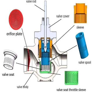
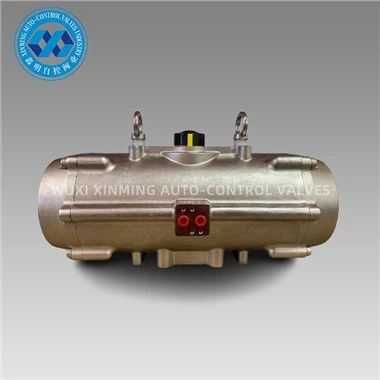
Main Components of a Pneumatic Valve
| Component | Function |
|---|---|
| Valve Body | Contains internal flow passages and supports all valve components. |
| Spool or Poppet | Controls airflow direction inside the valve. |
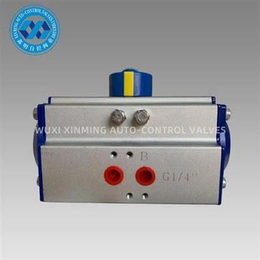
| Ports | Provide inlet, outlet, and exhaust connections. |
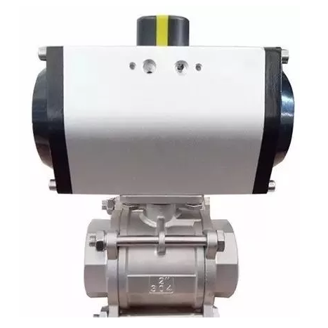
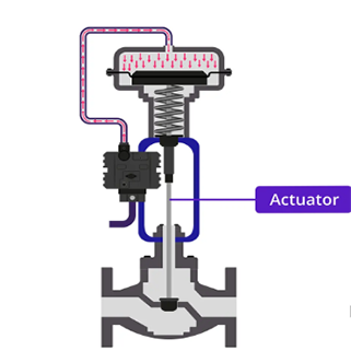
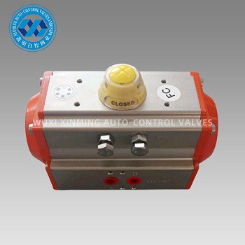
| Actuator | Activates valve movement using pneumatic, electric, or manual force. |
| Spring Return | Returns the valve to its default position after actuation. |
| Seals | Prevent air leakage and maintain pressure integrity. |
Basic Pneumatic Valve Diagram Example
The following simplified diagram shows a common 5/2-way pneumatic directional control valve used with double-acting pneumatic actuators.
In this configuration, compressed air alternates between Port A and Port B to extend or retract a pneumatic cylinder or rotary actuator.
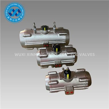
Common Pneumatic Valve Types
1. Directional Control Valves
Directional control valves regulate airflow direction within pneumatic systems. Common configurations include 2/2-way, 3/2-way, 5/2-way, and 5/3-way valves.
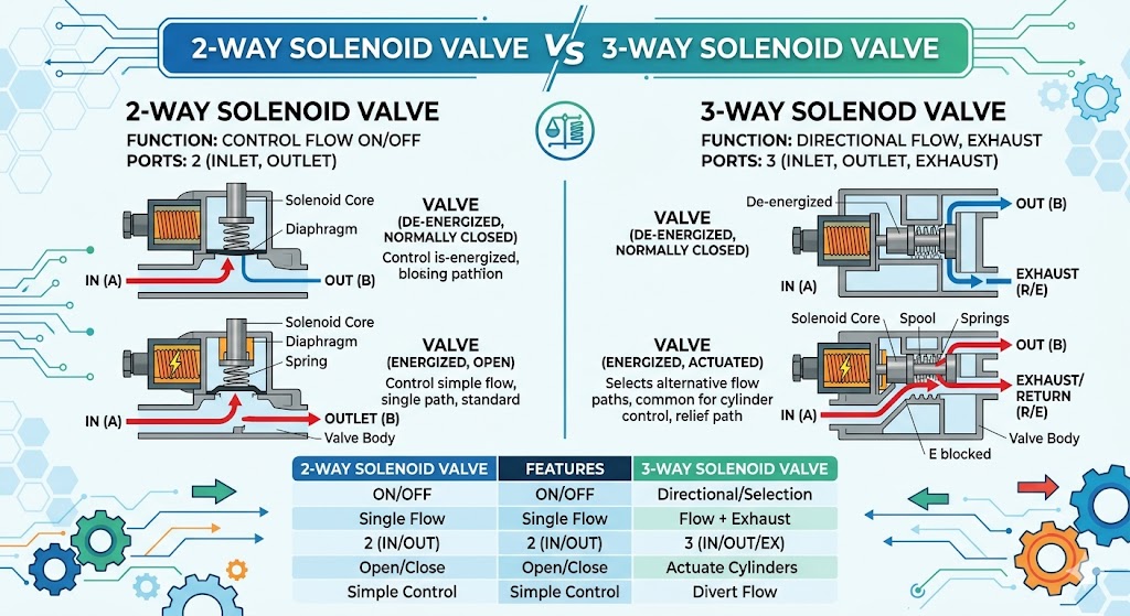
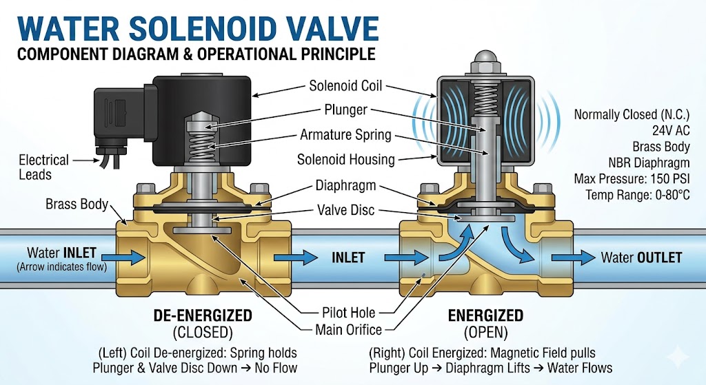
2. Solenoid Pneumatic Valves
Solenoid valves use electromagnetic coils to actuate internal valve mechanisms. They are commonly used in automated industrial systems because of their fast response and remote control capability.
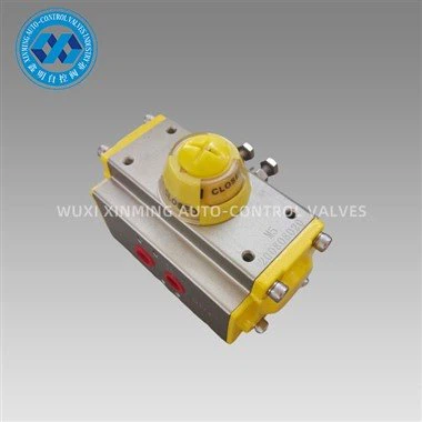
3. Manual Pneumatic Valves
Manual valves are operated by levers, push buttons, or pedals. These valves are frequently used in maintenance systems and emergency control circuits.
4. Air Pilot Valves
Air pilot valves use compressed air signals instead of electrical signals for operation. They are widely used in hazardous environments where electrical equipment may create safety risks.
Understanding Pneumatic Valve Symbols

Pneumatic valve diagrams use standardized symbols to represent valve functions and operating positions. The number of squares indicates valve positions, while arrows indicate airflow direction.
| Valve Symbol | Description |
|---|---|
| 2/2 Valve | Two ports and two positions for simple ON/OFF control. |
| 3/2 Valve | Three ports and two positions, often used with single-acting cylinders. |
| 5/2 Valve | Five ports and two positions for double-acting actuators. |
| 5/3 Valve | Five ports and three positions with center control functionality. |
How a Pneumatic Valve Works
A pneumatic valve controls the movement of compressed air through internal passages. When the actuator receives a signal, the internal spool shifts position, opening some flow paths while closing others.
- Compressed air enters through the supply port.
- The actuator shifts the spool or poppet.
- Air is redirected to the required output port.
- Unused air exits through exhaust ports.
- The valve returns to its original position after signal removal if spring-returned.
This operating principle enables precise control of pneumatic cylinders, rotary actuators, butterfly valves, ball valves, and other automation devices.
Industrial Applications of Pneumatic Valves

| Industry | Application |
|---|---|
| Oil & Gas | Automated valve control and emergency shutdown systems. |
| Water Treatment | Flow regulation and pneumatic actuator operation. |
| Food Processing | Sanitary automation systems and air-driven controls. |
| Power Plants | Instrument air control systems. |
| Manufacturing | Robotic automation and production line equipment. |
Advantages of Pneumatic Valve Systems

- Fast operating speed and response time.
- Simple installation and maintenance.
- Safe operation in explosive environments.
- Reliable automation performance.
- Cost-effective for industrial control systems.
- Long service life with minimal wear.
Common Problems Identified Through Pneumatic Valve Diagrams
Pneumatic valve diagrams are valuable for troubleshooting industrial pneumatic systems. Technicians can quickly locate airflow interruptions, incorrect port connections, or actuator failures.
| Problem | Possible Cause |
|---|---|
| Valve not shifting | Insufficient pilot pressure or solenoid failure. |
| Air leakage | Damaged seals or loose fittings. |
| Slow actuator movement | Restricted airflow or clogged exhaust ports. |
| Incorrect valve operation | Improper tubing connection or wiring issue. |
Conclusion
Pneumatic valve diagrams are fundamental tools for understanding industrial pneumatic systems and automated valve control. By learning pneumatic symbols, valve structures, and airflow paths, engineers and technicians can improve system efficiency, simplify maintenance, and ensure reliable automation performance.
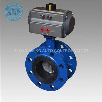
Whether used in pneumatic actuators, butterfly valves, ball valves, or solenoid valve systems, pneumatic valve diagrams provide critical technical insight for industrial operations worldwide.
If you want to learn more about low-priced products, please visit the following website: www.xm-valveactuator.com