Understanding P&ID Diagrams
Piping and Instrumentation Diagrams, commonly known as P&ID or P&ID drawings, serve as the lifeline of process engineering. These comprehensive diagrams illustrate the detailed piping design, process equipment, instrumentation, and control logic of a manufacturing or processing facility. Whether you are working in oil and gas, chemical processing, water treatment, or pharmaceutical industries, understanding P&ID symbols is fundamental to your engineering career.
The primary purpose of a P&ID diagram is to provide a clear, standardized representation of all process equipment, piping, valves, instruments, and control systems. Engineers, operators, and maintenance personnel rely on these diagrams daily to understand how a process functions, troubleshoot issues, plan modifications, and ensure safe operation of industrial facilities.
Essential Valve Symbols in P&ID
Valves are critical components in any process system, controlling flow, pressure, temperature, and level throughout the facility. P&ID valve symbols follow internationally recognized standards, primarily the ISA S5.1 standard and ISO 14617 standards, ensuring consistency across the global engineering community.

Gate Valve
A symbol representing a valve that uses a sliding gate to control flow. Gate valves provide minimal restriction when fully open and are commonly used for isolation applications.
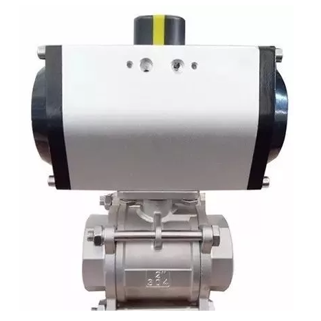
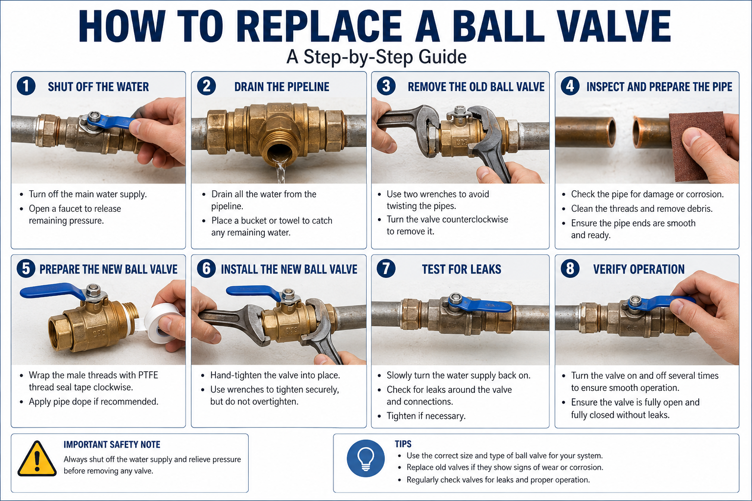
Ball Valve
Represented by a circle with a diagonal line, ball valves use a spherical disc to control flow. They offer quick operation and reliable sealing for on/off applications.
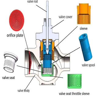
Globe Valve
Features a spherical or globular body shape. Globe valves provide precise throttling control and are ideal for flow regulation applications where accuracy is paramount.
Butterfly Valve
A circular symbol with a diagonal line representing a valve with a rotating disc. Butterfly valves are compact, lightweight, and suitable for large diameter piping applications.
Check Valve
Also known as non-return valves, these symbols show flow in one direction only. Critical for preventing backflow and protecting equipment from damage.
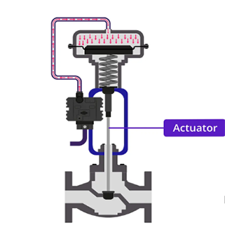
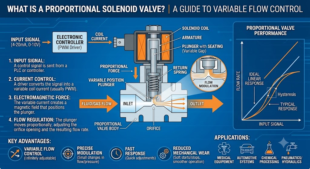
Control Valve
Actuated valves that automatically调节 process variables. Control valve symbols include the valve body plus actuator and positioner information.
Valve Symbol Standards and Conventions
Understanding the visual language of P&ID symbols is essential for accurate interpretation. Each valve type has a distinct symbolic representation that conveys critical information about its function, operation method, and connection specifications.
Key Symbol Components
Common Valve Types and Their Applications
Different process conditions require different valve types, and the P&ID must accurately represent which valve is specified for each application. This ensures that construction, operation, and maintenance personnel all understand the design intent.
| Valve Type | Primary Function | Typical Application |
|---|---|---|
| Isolation Valve | Complete flow stoppage | Maintenance isolation, emergency shutdown |
| Throttling Valve | Precise flow control | Flow regulation, pressure control |
| Check Valve | Prevent backflow | Pump protection, backflow prevention |
| Pressure Relief Valve | Overpressure protection | System safety, equipment protection |
| Modulating Valve | Variable position control | Continuous process control loops |
Reading and Interpreting P&ID Valve Symbols
Professional engineers must develop fluency in reading P&ID diagrams quickly and accurately. The ability to interpret valve symbols correctly is critical for safe plant operation, efficient maintenance planning, and accurate troubleshooting.
Step-by-Step Identification Process
When encountering an unfamiliar valve symbol on a P&ID, follow this systematic approach to ensure accurate identification and understanding of the component's purpose in the overall system.
Identification Checklist
Industry Standards for P&ID Symbols
The engineering profession has established comprehensive standards to ensure consistency in P&ID documentation. Adhering to these standards facilitates clear communication among engineers, contractors, operators, and regulatory bodies across international boundaries.
The Instrumentation, Systems, and Automation Society (ISA) provides the most widely recognized standard for instrumentation symbols through ISA-5.1. This standard defines symbols for instruments, valves, actuators, and control functions. European and international projects often reference ISO 14617 for graphical symbols in technical diagrams and drawings.
Best Practices for P&ID Development
Creating accurate and clear P&ID diagrams requires attention to detail and adherence to established conventions. Well-developed P&IDs reduce errors, improve communication, and facilitate efficient plant operations throughout the facility lifecycle.
Professional Guidelines
Advanced Valve Symbol Modifiers
Beyond basic valve symbols, P&ID diagrams often include various modifiers that provide additional information about valve functionality, position feedback, and control characteristics. Understanding these modifiers is essential for interpreting modern process control systems.
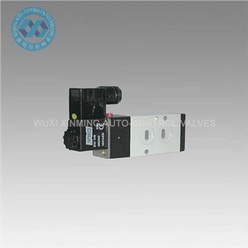
Smart valve positioners, solenoid valves, hand wheels, limit switches, and other auxiliary devices are all represented through specific symbol additions. These modifiers transform simple isolation valves into sophisticated control elements capable of communicating with distributed control systems.
Digital P&ID and Symbol Libraries
Modern engineering workflows utilize computer-aided design software with comprehensive symbol libraries. These digital tools ensure consistency, enable easy updates, and facilitate the integration of P&ID data with other engineering information systems.
Popular engineering software platforms include AutoCAD PID, SmartPlant P&ID, AVEVA Diagrams, and various plant design management systems. Each platform provides standardized symbol libraries that comply with relevant industry standards while offering customization options for project-specific requirements.
Conclusion
Mastering P&ID and valve symbols is an essential skill for every process engineer and instrumentation professional. The standardized visual language of piping and instrumentation diagrams enables clear communication across disciplines, languages, and international boundaries. By understanding the fundamental symbols, their modifiers, and the standards that govern them, you can effectively read, interpret, and create P&ID documentation that supports safe, efficient plant operations.
Whether you are specifying valves for a new project, troubleshooting process issues, or planning maintenance activities, a thorough understanding of P&ID valve symbols will enhance your professional capabilities and contribute to successful engineering outcomes.