In the world of industrial automation, pneumatic symbols are the universal language of fluid power. Whether you are designing a complex assembly line or troubleshooting a faulty actuator, being able to "read" a schematic is the difference between a quick fix and hours of downtime.
This guide breaks down the essential symbols based on ISO 1219 standards, ensuring you can interpret any pneumatic circuit with confidence.
Why Standardization Matters: ISO 1219
Pneumatic systems rely on international standards to ensure safety and interoperability. The ISO 1219-1 and ISO 1219-2 standards define the symbols used for fluid power systems. By using these standardized icons, an engineer in Germany can seamlessly understand a circuit designed in Japan or the United States.
1. Directional Control Valve Symbols
Valves are the "brains" of the system, directing the flow of compressed air. To understand a valve symbol, you need to look at two things: Positions and Ways.
- Squares (Positions): Each square represents a state of the valve (e.g., "on" or "off").
- Arrows (Flow): Inside the squares, arrows indicate the direction of air flow.
- T-Lines (Blocked): A "T" shape indicates a port that is currently blocked.
Common Valve Types
| Valve Type | Description | Common Application |
|---|---|---|
| 2/2 Valve | 2 Ports, 2 Positions | Simple On/Off control. |
| 3/2 Valve | 3 Ports, 2 Positions | Controlling single-acting cylinders. |
| 5/2 Valve | 5 Ports, 2 Positions | Controlling double-acting cylinders. |
| 5/3 Valve | 5 Ports, 3 Positions | Allows a cylinder to "stop" or "float" in the middle of a stroke. |
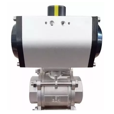
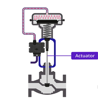
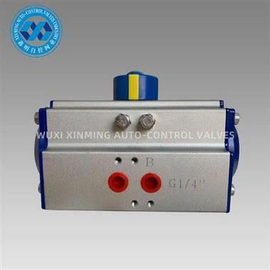
2. Pneumatic Actuators: The Muscle
Actuators convert the energy of compressed air into mechanical motion. Their symbols are generally intuitive, depicting a piston inside a barrel.
-
Single-Acting Cylinder: Features one air port and a spring return. The symbol shows a zigzag line (spring) on one side.

-
Double-Acting Cylinder: Features two ports, allowing air to drive the piston in both directions (extend and retract).

- Cushioned Cylinders: Symbols with a small rectangle or "slash" at the end of the stroke indicate internal cushioning to prevent impact damage.
3. Air Preparation (FRL Units)
Before air reaches the valves, it must be "conditioned." This is handled by the FRL unit (Filter, Regulator, Lubricator).
- Filter: A diamond shape with a dashed line across the center (representing the element).
- Regulator: A square with an arrow pointing to a dashed line, often accompanied by a circle (the gauge).
- Lubricator: A diamond with a small vertical line, indicating oil mist being added to the air.
Pro Tip: In modern schematics, you will often see a "Simplified FRL Symbol," which combines all three components into a single diamond shape to save space.
4. Lines and Connections
How the components are linked is just as important as the components themselves.
- Solid Line: A working line (conveys main air flow).
- Dashed Line: A pilot line (used for control signals).
- Dotted Line: A drain or exhaust line.
- Intersection with a Dot: Indicates a physical connection between two lines.
- Intersection without a Dot: Indicates lines crossing over each other without connecting.
5. Frequently Asked Questions (FAQ)
How do I read a pneumatic valve symbol?
Start by counting the squares to determine the number of positions. Then, count the points where the lines touch the square in the "home" position to determine the number of ports (ways).
What is the difference between a pilot signal and a manual override?
A pilot signal (dashed line) uses air pressure to switch the valve, whereas a manual override (a button or lever icon) requires human intervention.
Why is there a triangle on the bottom of my valve symbol?
A triangle pointing outward indicates an exhaust port. If the triangle is filled, it usually denotes a hydraulic return; if it is an outline, it represents air exhausting to the atmosphere.
Conclusion
Mastering pneumatic symbols is an essential skill for anyone involved in mechanical engineering or industrial maintenance. By focusing on the logic of ISO 1219, you can deconstruct even the most intimidating blueprints into a series of simple, logical steps.
If you want to learn more about low-priced products, please visit the following website: www.xm-valveactuator.com